Logic gates form the core of digital electronics. From the simplest calculator to the most advanced supercomputer, everything depends on these tiny decision-making circuits. If you want to understand how computers think and operate, getting a solid grasp of logic gates is essential. In this guide, we’ll explore the seven fundamental logic gates: AND, OR, NOT, NAND, NOR, XOR, and XNOR — their functions, symbols, truth tables, and where they are used.
What Are Logic Gates?
Logic gates are electronic devices that take one or more binary inputs (0 or 1) and produce a single binary output based on a logical operation. These operations are the foundation of all digital systems, allowing machines to process data, make decisions, and perform calculations.
AND Gate – All Conditions Must Be True
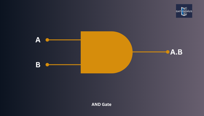
The AND gate outputs 1 only when all inputs are 1; otherwise, it outputs 0. Think of it as a strict rule where every condition must be met to get a The AND gate outputs 1 only when all inputs are 1; otherwise, it outputs 0. Think of it as a strict rule where every condition must be met to get a positive result. In other words, if even one input is 0, the output will be 0. This behavior makes the AND gate useful in situations where multiple criteria must be satisfied simultaneously.
For example, imagine a security system where two sensors must both detect motion before triggering an alarm. The system uses an AND gate: only when both sensors send a signal (1), the alarm activates (output 1). If either sensor is inactive (0), the alarm stays silent.
In digital circuits, AND gates are used to enable operations only when all necessary control signals are active. This ensures precise control and coordination among different parts of a system.
Truth Table:
| A | B | Output (A AND B) |
|---|---|---|
| 0 | 0 | 0 |
| 0 | 1 | 0 |
| 1 | 0 | 0 |
| 1 | 1 | 1 |
The AND gate’s fundamental role in combining conditions makes it essential in arithmetic operations, decision making, and logic implementations throughout digital electronics.
OR Gate – Any Condition is Enough
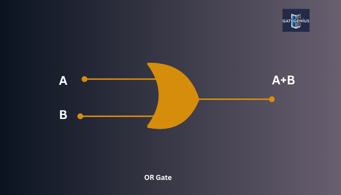
The OR gate outputs 1 if at least one input is 1. It’s more flexible — just one “yes” is enough to get a positive output.
Truth Table:
| A | B | Output |
|---|---|---|
| 0 | 0 | 0 |
| 0 | 1 | 1 |
| 1 | 0 | 1 |
| 1 | 1 | 1 |
Example: If any switch is ON, the light turns ON.
NOT Gate – The Inverter
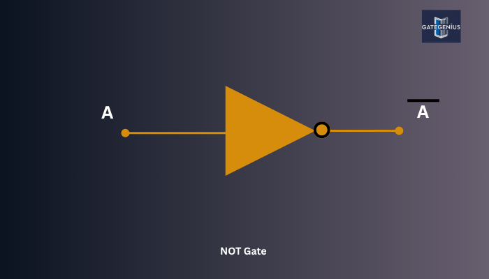
The NOT gate takes a single input and reverses it. If the input is 0, the output is 1, and vice versa.
Truth Table:
| A | Output |
|---|---|
| 0 | 1 |
| 1 | 0 |
Example: If the switch is OFF, the light is ON.
NAND Gate
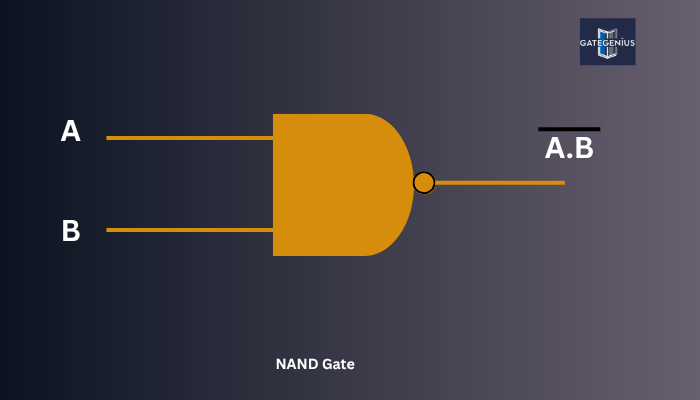
The NAND gate is the opposite of AND. It outputs 0 only when all inputs are 1; otherwise, it outputs 1. Because of its versatility, it’s called a universal gate, meaning you can build any other gate using only NAND gates.
Truth Table:
| A | B | Output |
|---|---|---|
| 0 | 0 | 1 |
| 0 | 1 | 1 |
| 1 | 0 | 1 |
| 1 | 1 | 0 |
NOR Gate
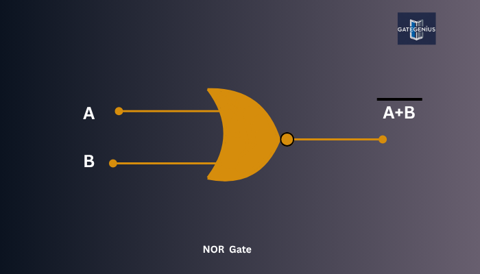
The NOR gate is the opposite of OR. It outputs 1 only when all inputs are 0; otherwise, it outputs 0. It is also a universal gate and widely used in digital logic.
Truth Table:
| A | B | Output |
|---|---|---|
| 0 | 0 | 1 |
| 0 | 1 | 0 |
| 1 | 0 | 0 |
| 1 | 1 | 0 |
XOR Gate – The Exclusive Decision Maker
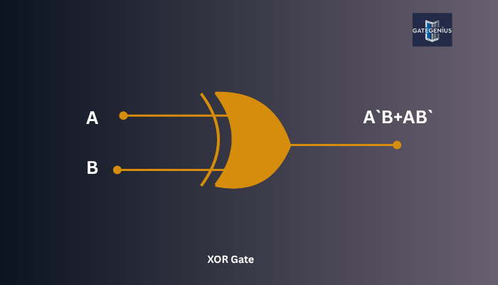
The XOR (Exclusive OR) gate outputs 1 only when the inputs are different. If inputs are the same, the output is 0. This makes XOR useful for error detection and arithmetic operations.
Truth Table:
| A | B | Output |
|---|---|---|
| 0 | 0 | 0 |
| 0 | 1 | 1 |
| 1 | 0 | 1 |
| 1 | 1 | 0 |
XNOR Gate – The Equality Checker
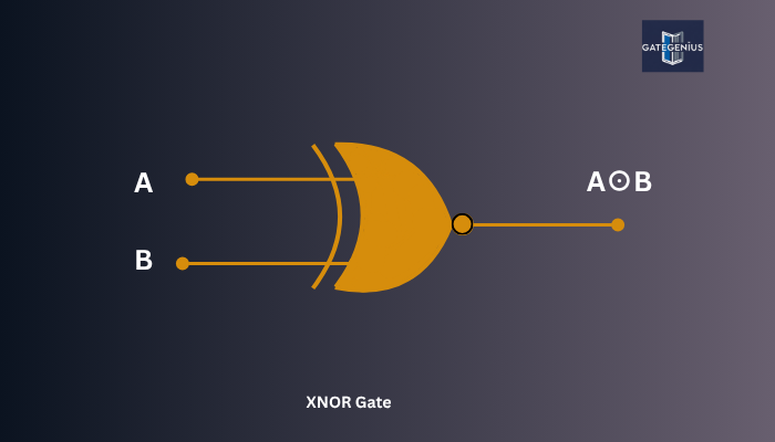
The XNOR (Exclusive NOR) gate is the opposite of XOR. It outputs 1 when inputs are the same and 0 when they differ. It’s used in equality comparators.
Truth Table:
| A | B | Output |
|---|---|---|
| 0 | 0 | 1 |
| 0 | 1 | 0 |
| 1 | 0 | 0 |
| 1 | 1 | 1 |
Summary of Logic Gates
| Gate | Symbol | Function | Output Condition |
|---|---|---|---|
| AND | · | Output 1 if all inputs are 1 | Strict all-true condition |
| OR | + | Output 1 if any input is 1 | Flexible any-true condition |
| NOT | ′ | Output is the opposite input | Inversion |
| NAND | ↑ | Output 0 only if all inputs 1 | Opposite of AND |
| NOR | ↓ | Output 1 only if all inputs 0 | Opposite of OR |
| XOR | ⊕ | Output 1 if inputs differ | Exclusive OR |
| XNOR | ⊙ | Output 1 if inputs are same | Exclusive NOR |
Why Are Logic Gates Important?
Logic gates in digital electronics are the fundamental components that drive the operation of all modern digital systems. From processing information to making decisions and storing data, logic gates form the backbone of how digital devices work. Their ability to perform logical operations allows complex hardware and software systems to function seamlessly. Below are key areas where logic gates are essential:
1. Arithmetic Calculations in Processors
Logic gates perform binary arithmetic within processors — the core unit of any computer or microcontroller. Using a combination of AND, OR, NOT, XOR, and XNOR gates, engineers design arithmetic logic units (ALUs) capable of carrying out addition, subtraction, multiplication, and division. For example, half adders and full adders use logic gates to add binary numbers, forming the basis of all mathematical operations in CPUs.
2. Decision Making in Control Systems
Control systems in appliances, industrial machinery, robotics, and vehicles rely on logic gates in digital electronics to evaluate input conditions and make real-time decisions. These gates process signals from sensors and user inputs to control operations. For example, in a smart washing machine, logic gates can determine the washing mode based on load size and dirt level inputs.
3. Data Storage and Memory Management
Storage devices use circuits built with NAND and NOR gates to create flip-flops — the basic memory elements. These flip-flops store one bit of data and are combined to form larger memory units like RAM and registers. Logic gates also play a role in managing read/write operations, data flow, and synchronization between memory and processing units.
4. Error Detection and Correction in Communications
In digital communication systems, maintaining data integrity is critical. Logic gates, especially XOR and XNOR, are used in parity checkers and cyclic redundancy check (CRC) circuits to detect and correct errors during data transmission. These mechanisms ensure that the information received is exactly what was sent, making communication systems more reliable.
5. Implementation of Logic Circuits
Every digital circuit, from a simple door lock system to a complex microcontroller, is constructed by combining various logic gates. Designers use Boolean algebra to create logic expressions, which are then implemented using physical gates. This process allows custom circuit design for tasks like timing, signal routing, and conditional execution.
6. Building Sequential Circuits
Sequential circuits, which include counters, timers, registers, and state machines, depend on logic gates along with clock signals to produce output based on present and past inputs. Unlike combinational logic, these circuits store information, enabling memory and time-based behavior in devices such as digital clocks, traffic light controllers, and calculators.
7. Enabling Programmable Logic Devices
Programmable Logic Devices (PLDs) like FPGAs (Field Programmable Gate Arrays) and CPLDs (Complex PLDs) are designed using networks of logic gates. These devices allow engineers to reprogram hardware behavior using code, offering flexibility and reusability in embedded systems, IoT devices, and prototyping.
8. Logic in Artificial Intelligence and Automation
In automation systems and embedded AI applications, logic gates in digital electronics are used for low-level decision making. While higher-level AI relies on algorithms and models, the physical operations still run through logic gate-based processors, microcontrollers, and digital signal processors (DSPs).
Frequently Asked Questions?
Q1. What are logic gates in digital electronics?
A1. Logic gates are basic building blocks of digital circuits that perform logical operations on binary inputs (0s and 1s) and produce a binary output. They are used to create complex decision-making and data-processing systems.
Q2. What are the main types of logic gates?
A2. The main types of logic gates are:
AND, OR, NOT, NAND, NOR, XOR, XNOR.
Each gate has a unique truth table and behavior.
Q3. What is the difference between combinational and sequential logic?
A3. Combinational logic produces output based only on current inputs, while sequential logic also considers past inputs (using memory elements like flip-flops). Logic gates are used in both types.
Q4. What is a truth table in logic gates?
A4. A truth table is a table that lists all possible combinations of inputs and their corresponding outputs for a logic gate. It helps in understanding how the gate works.
Q5. Why are NAND and NOR gates called universal gates?
A5. NAND and NOR gates are called universal gates because any other gate (AND, OR, NOT, etc.) can be constructed using only NAND or only NOR gates.
Q6. How are logic gates used in real life?
A6. Logic gates are used in:
- Computers and mobile processors
- Control systems like elevators and traffic lights
- Memory storage devices
- Digital watches and calculators
- Home appliances like washing machines and microwaves
Q7. What is the function of the XOR gate?
A7. The XOR (Exclusive OR) gate outputs 1 only when exactly one of the inputs is 1. If both inputs are the same (0 and 0 or 1 and 1), the output is 0.
Conclusion
Understanding Logic Gates Digital Electronics is essential for anyone stepping into the world of digital systems and electronics. These gates may seem simple, but they are the core components that make complex devices function — from tiny microcontrollers to powerful processors. Every digital decision, calculation, or memory operation begins with a combination of logic gates working behind the scenes.
By mastering the behavior and application of Logic Gates in Digital Electronics, you gain the ability to design, analyze, and troubleshoot circuits with confidence. This knowledge not only helps in academic exams like GATE and UGC NET, but also builds a strong base for careers in embedded systems, robotics, computer architecture, and VLSI design.
I hope you understand the Mastering Logic Gates Digital Electronics: The Building Blocks of Digital Electronics. So don’t forget to share this post with friends and anyone preparing for the GATE, UGC NET exams, or studying at the university.